
Winner By A Nose!
Wiper technology is designed to improve surface finish in machining applications. It involves an insert with a flat. As the 'wiper' passes through the cut, it smoothes the surface.

Share


Application of wiper technology to turning operations allows shops to double current feed rates without diminishing surface finish. Conversely, maintaining current feed rates will give two times better surface finish.
The top illistration shows a conventional insert with a single tool nose radius (rE). Keeping the feed rate (fn) constant will improve surface finish (rt) by a factor of 2X. As shown in the third illustration, doubling the feed rate produces no change in surface finish.
For some time, cutting tool manufacturers have offered an innovative insert geometry called "wiper" on milling inserts. In operation, "wiper" technology is designed to improve surface finish in milling applications. It works by positioning an insert with a flat just below the other ordinary parallel land inserts on a face mill. As the "wiper" passes through the cut, it smoothes the surface.
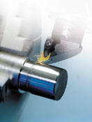
That's fine for flat milling. But for turning, the idea of wiper is more complex because of the contouring and shoulder work that is done on a lathe. That said, it looks like Sandvik Coromant (Fair Lawn, New Jersey) has managed to create "wiper" technology for use on turning operations.


According to the company, for turning shops looking to boost metal removal rates without programming a change in speed or depth of cut, these semi-finishing and finishing inserts can be run at least double the nominal feed rate for standard indexable inserts. Or, wiper inserts run at current feeds and speeds will produce roughness averages around half of conventional inserts.
Most turning jobs specify a specific radius for corners, steps, shoulders and other features. This specification translates into the tool nose radius of the cutting insert. It may be 1/64th , 1/32nd or other radii.
As a conventional single radius insert is fed through the work, it creates scallops in the surface of the part. These scallops are roughly equivalent to the tool nose radius.
To get a smooth finish, the "peaks" or high points of the scallops need to be smoothed. That's where "wiper" technology comes into the picture.
Instead of taking multiple finish passes to reduce the high points of the scallops, wiper technology is designed to accomplish this in a single pass. Moreover, it's a single pass that generally can be run at twice the feed rate of a conventional finish pass.
What Sandvik has done is take an insert with a standard nose radius and added additional geometry behind the lead cutting edge. In operation, this geometry follows the tool nose with a "wiping" effect that knocks off the peaks of the scallops created by the leading edge. It allows the insert to move much faster through a cut with no reduction in surface finish.
An advantage to users is that the new insert design is a "drop-in" for conventional inserts. If the job is running with a number one tool nose radius, that specification is unchanged with the new wiper design. It is generally not necessary to re-qualify the process.
The company says the production advantages for these new inserts are dramatic. Shops have a choice of how to use the wiper to achieve either double the current feed rates used on a job or run the job at current feed and reduce by half the surface finish number of the current process.
Putting more parts across a machine tool is a desirable goal for most shops. Because tool wear is measured as time in the cut, doubling the feed rates on these inserts allows more parts per edge to be manufactured. Extended tool life is the result.
On the other hand, if the surface finish requirement is 64 microinch and dropping in the wiper insert gives 30 microinch, tools can be left in the machine until they are dulled down to the 64 microinch specification, extending the effective cutting life of a given insert.
Turning applications in general have relatively short cycle times. In most cases, it takes something fairly dramatic to make a significant impact on the production rate in turning and for a shop to justify a process change.
Sandvik promises a minimum of 20 percent increase in feed rates with no surface finish change by substituting these new inserts. They also require no change in process parameters except to adjust the feed override—by a factor of 2X!


Related Content

Walter Ceramic Inserts Enable Efficient Turning, Milling
Suitable turning and milling applications of the WIS30 ceramic grade include roughing, semi-finishing and finishing, as well as interrupted cuts.
Read More
Picking the Right End Mill
Kennametal global product manager Katie Myers explains how cutting tool features can impact machining strategies for different materials.
Read More

Sandvik Coromant Milling Tool Boosts Productivity in Steel Machining
CoroMill MR80 is designed for challenging roughing operations in a wide range of face and profile milling applications in steel and stainless steel.
Read More