
The Case for the Perpendicular Indicator
In most cases, a standard or dial indicator is adequate for gaging requirements. However, sometimes the normal orientation of a standard indicator does not work for a particular application. In this situation, a perpendicular indicator might be the better choice.

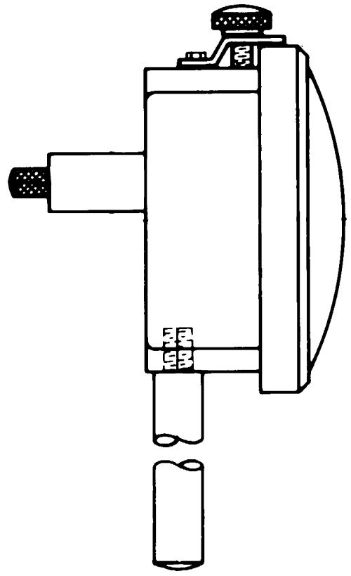
The typical configuration of a dial indicator features a sensitive contact in line with the face of the indicator. Typically, an upward movement of the contact represents a larger value on the face of the indicator.
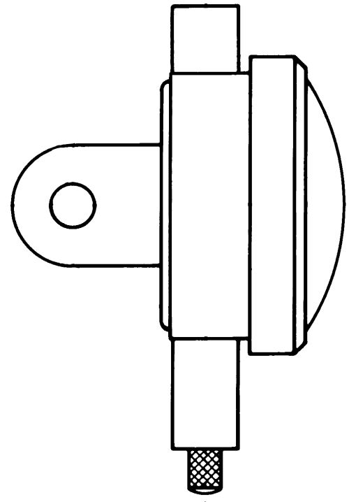
With a perpendicular indicator, the sensitive contact is at a right angle to the face of the indicator, and an inward movement of the contact toward the face of the indicator represents a positive value.
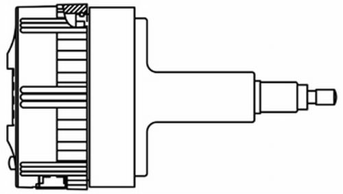
With the short range digital indicators commonly seen on comparative style gages, the transducer is a stand-alone item. It can be moved out of its standard case and mounted in a special back on the rear of the normal display. Thus, the indicator looks and acts like it always does, but the transducer is now perpendicular to the back in a very compact package.
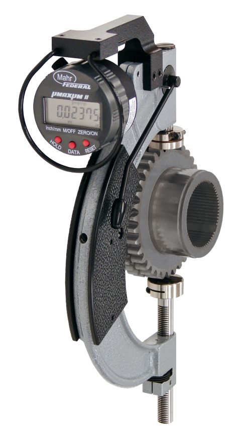
In the case of this gear gage, it was important to measure the part while still mounted in the machine. By applying a perpendicular digital comparator to the existing mounting, the operator can clearly see the size and make the appropriate decision.
Share


One final note: the April print issue marks the 20th anniversary of the Quality Gaging Tips column. That is perhaps not such a milestone in the greater scheme of things, but it has given me a very good perspective on the topic of dimensional gaging as a whole. While most of the things we talk about here are tactical, problem-solving matters, it is also clear that there are some larger trends driving the process. We’ll be discussing those in a special “Trends in Dimensional Gaging” feature in next month’s issue. I hope you check it out.


.png;maxWidth=300;quality=90;format=webp)


