
Applying A High Speed Machining Discipline Without The Speed
In this shop, high speed machining makes sense at 4,000 rpm. While the disciplines the shop put in place made a new 15,000-rpm profiler dramatically more productive, high speed machining would have remained valuable even if the new machine never came. Acoording to a co-owner of this shop, high speed machining has no need for speed.
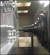
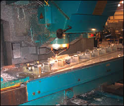
This view shows the inside of the shop’s most productive machine tool, an SNK five-axis profiler. With the shop already applying high speed machining disciplines on its existing machines, the existing programs and processes were readily adapted to this faster machine. As a result, the shop was able to begin profiting from the machine almost as soon as it hit the floor.
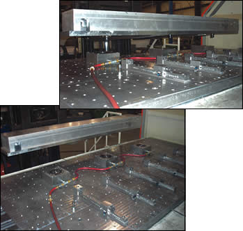
The machine’s spindle is horizontal, but the worktable pivots to lie flat so the machine can be loaded like a vertical. The shop’s use of self-locating Unilock workholding devices further simplifies part loading, allowing the raw stock for a new job to be quickly and accurately locked in place.
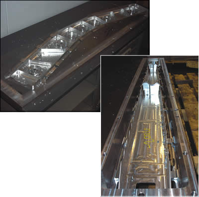
The shop specializes in parts like these—aircraft structural components machined out of blocks of aluminum or titanium.
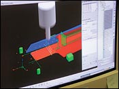
High speed machining disciplines often demand seemingly unusual tool paths.
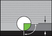
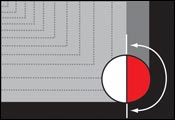
A half-width cut turns into a full-width cut in the corner. Instead of allowing the cut to become overloaded, why not just assume a full-width cut throughout the cycle?
High speed machining makes sense even if the speed isn’t there. On older, slower machines, the benefits of adhering to high speed machining disciplines include a more consistent process, better surface finish and less need for deburring.
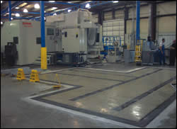
The shop will buy another profiler identical to its current one, and the two machines together will form the core of a high speed machining cell. This cell will be one of the most productive areas in the shop, as well as perhaps the least demanding in terms of the amount of operator attention required.
Share


Jerry Halley, engineering vice president for Tech Manufacturing in Wright City, Missouri, has three basic rules for machining a part through high speed machining. Those rules are:
- Cut at small axial depths of cut, and take those cuts as fast as you can.
- Ensure that the work is as stiff as you can make it in the place where you are cutting.
- Once you’ve cut a feature, don’t return to that feature again.
Payoff: Predictability
Mr. Halley once worked for Boeing. During the previous decade, he was part of a group of manufacturing engineers at the company’s St. Louis facility that made high-rpm milling machines both more capable and more productive by applying high speed machining disciplines to the way they were used.


In that context—that is, milling aircraft structural shapes out of solid blocks of aluminum and titanium—“high speed machining” has a specific meaning related to chatter. Higher-rpm machining centers all have built-in chatter tendencies, and that chatter can limit the machine’s productivity in high-metal-removal applications. However, understanding the chatter can also facilitate a high-metal-removal rate, provided the shop can find just the right spindle speed at which the milling process quiets down at a relatively high rpm. These optimum speeds are different for every different combination of tool and spindle. By finding the optimum speeds and applying disciplines such as the ones above, the Boeing facility was able to make its machines not only more productive, but also better able to remove the cost and weight from aircraft parts by machining thin walls and floors productively.
Now, as a co-owner of Tech Manufacturing, a job shop that has served the aerospace industry for longer than 50 years, Mr. Halley applies the high speed machining disciplines to almost all of the aircraft workpieces machined on the shop’s various five-axis and three-axis machining centers. At fewer than 50 employees and a dozen CNC machines, he says his shop may well be the smallest one to be this devoted to high speed machining. Strictly in terms of the top speeds of his shop’s equipment, his is probably the slowest shop to be devoted to high speed machining as well.
The speed (or lack of it) doesn’t necessarily matter. Look again at the rules cited above. They don’t require any particular speed. The rule about “as fast as you can” can still be applied, even if this isn’t particularly fast.
Most of Tech Manufacturing’s five-axis machining centers are limited to a top speed of 4,000 rpm. Though the shop has maintained the machines well and they are still very capable, these are older machines. At the speeds they can reach, the chance to achieve dramatically greater productivity by finding a special chatter-free spindle speed does not exist. However, the disciplines and procedures related to high speed machining can still be applied to these machines—and Mr. Halley applies them.
A big payoff came last year when the shop added its newest five-axis machine—an HPS 120B/5 profiler from SNK America that is capable of 15,000 rpm. Through vibration-analysis testing using the MetalMax system from Manufacturing Laboratories Inc., Mr. Halley measured the frequency response characteristics for this machine to determine its ideal high-productivity spindle speeds for various standard tools in the shop. With this information, he determined new speeds, feed rates and depths of cut for programs to be run on the machine, but he didn’t have to change any tool paths. High speed machining tool paths that were already being run productively on the older machines could now be run even more productively on the new machine. The machine started making money for the shop almost as soon as it hit the floor.
Yet this payoff was not essential, Mr. Halley says. High speed machining still would have made sense for the shop if the new machine never came. While the term “high speed machining” may be a bit of a misnomer when the speed is low, machining in ways that observe these disciplines provides benefits related to process consistency and predictability. According to Mr. Halley and the rest of Tech Manufacturing, high speed machining provides value even when the speed isn’t there.
Eliminating Variables
In fact, the disciplines of high speed machining are not about any particular speed as much as they are about optimization.
The typical approach to machining aircraft structural components and other high-metal-removal parts goes like this: The roughing operation goes quickly, as a lot of material is hogged out with a big tool. Then, the finishing operation takes considerably more time, as critical features are cut in small layers to ensure accuracy. Vibration invariably adds to the uncertainty of finish passes, as one factor or another affects the dynamic stability of the process at that particular moment on that particular day.
An effective high speed machining process limits variables so that the remaining variables can all be optimized to make the cut as stable and productive as possible. Choice is not necessarily good, because too vast of a range of choices makes the process too difficult to control.
For example, the number of milling tools available to the shop is deliberately limited to a small amount. At Tech Manufacturing, just four standard end mill styles account for the vast majority of the shop’s work. Tool lengths are limited, too. Tools are all set to a standard gage length. No tool setting probe is needed, because tool gage length is a fixed value in this process.
The reason high spindle speed goes hand-in-hand with this kind of discipline is that small variations in the process can have pronounced effects on the system’s dynamic response. The special, high-productivity spindle speeds that the shop has found for its newest machine will only remain constant if the physics of the process remain constant as well.
At lower speeds, it may not be possible to find these special speeds. However, harmful chatter is still a danger. Here, the consistency of the process still makes it possible to fine-tune cutting parameters in order to minimize the chatter that does occur. At low speeds, the resulting process probably is not more or less productive in terms of cycle time when compared with a more typical process, but the carefully controlled process does deliver a better surface finish and less need for deburring.
Mr. Halley says there is yet another significant way the disciplined process reduces the number of variables—that is, by eliminating the distinction between roughing and finishing. In high speed machining, there are simply milling passes. If the cut is stable enough, then the same type of pass that removes material from the center of a pocket can also be the type of pass that machines the pocket’s wall to its final position.
Toolpath Technique
Stability also drives the way tool paths are chosen in high speed machining. Once a feature is machined, it is not touched again (see rule 3). Therefore, if the cutter leaves a flexible feature behind it as it finishes cutting a particular region, then this shouldn’t matter. However, the feature that is being cut should preserve enough stock in strategic places to support the feature as it emerges from the machined stock. Eliminating the distinction between roughing and finishing goes a long way toward helping with this, because the amount of stock left over for the final pass remains quite large. A thin wall, for example, can remain supported on both sides by a heavy stock envelope that is machined first on one side, then on the other, in alternating increments all the way down to the bottom.
Methodologies such as this are common sense once the need to maintain stiffness is understood, Mr. Halley says. However, the challenge in applying high speed machining methodologies is that CAM software tends not to support them. Automatically generated tool paths tend to machine away a particular volume in a pattern that is simply mathematically convenient, with no allowance made for the deflection or dynamics of the system. An example relates to the way Tech Manufacturing machines an unsupported thin floor. For stiffness, the best approach is to machine all the way down to the floor in one vertical layer, then step over and machine all the way down in an adjacent vertical layer, and so on. The accompanying video, near the top of this page, illustrates this toolpath strategy. (The video is part of a toolpath verification routine performed using Vericut software from CGTech.) By contrast, the shop’s programming software does not offer the option to machine pocket-like features in this way. Its automatically generated tool paths machine away the volume in horizontal increments instead—milling away the complete shape of the feature in one horizontal layer after another. Programmers therefore have to manually manipulate the automatic toolpath generation, treating each vertical increment as a separate machining operation. Manipulations like this produce a more consistent and predictable machining program that ultimately saves the shop trouble on the shop floor, even at low speeds—but the manipulations do result in increased programming time.
In fact, the amount of programming time required for high-speed-machined parts represents a challenge to using the shop’s new higher-speed profiler effectively. The machine speeds through parts, but the extra time required for programming creates the danger of the machine being left waiting for a needed program if the shop is not careful in how it schedules the machine.
Can Better Be Worse?
The new profiler is easily the most productive machine in the shop. The shop complements the machine’s short cycle times with short setup times, which are achieved using self-locking, self-locating workholding devices from BIG Kasier (see photo). At the chatter-free cutting speeds the shop has found for this machine, the profiler blows through the high speed machining programs that have already been proven out on the much slower five-axis machines.
Mr. Halley performed a frequency-response test on this machine before the shop bought it. He evaluated each machine the shop was considering by using the MetalMax system mentioned above. As familiar as he is with the impact and importance of a machine’s dynamic characteristics, he considers buying a machine without this analysis equivalent to buying a car without a test drive. One of the main things he was looking for was consistency in the vibration characteristics across the machine’s speed range. If there was no such consistency, it would mean the dynamics of the machine fundamentally changed as the speed changed—a situation that would make it difficult to find and maintain optimum speeds.
The machine has to be kept running productively because it represents such a large investment for the shop. An hour lost is one less hour toward making the payment on the machine, Mr. Halley says. Still, the shop is ready to make this investment again. While the machine may be the most expensive in the shop, it is also the least demanding in terms of the labor hours needed. When the shop buys a second profiler, the two machines will make up a high speed machining cell that will also include a deburring station. Two employees will be sufficient to tend this cell, he says—one experienced machinist plus one inexperienced employee, who will become more experienced over time by working alongside the more senior one.
The second profiler will be the same as the first one. In fact, it needs to be identical, so that all of the shop’s efforts at optimization can cleanly and immediately be applied to the new machine. Anything else would introduce variation, which would impede the shop from applying high speed machining effectively. According to Mr. Halley, the shop would not accept the second machine even if it was a little bit better.

.png;maxWidth=300;quality=90;format=webp)


Related Content

Addressing Manufacturing Challenges with Automation
GrayMatter Robotics’ Physical AI robotic cells for manufacturing offer immediate impact and results.
Read More
Additive/Subtractive Hybrid CNC Machine Tools Continue to Make Gains (Includes Video)
The hybrid machine tool is an idea that continues to advance. Two important developments of recent years expand the possibilities for this platform.
Read More
Orthopedic Event Discusses Manufacturing Strategies
At the seminar, representatives from multiple companies discussed strategies for making orthopedic devices accurately and efficiently.
Read More
Ballbar Testing Benefits Low-Volume Manufacturing
Thanks to ballbar testing with a Renishaw QC20-W, the Autodesk Technology Centers now have more confidence in their machine tools.
Read MoreRead Next

Ten Questions About Chatter
If you want to use a high speed milling spindle to machine aggressively, then information about chatter should be more than just background noise. Here are some basics.
Read More