
How to Save Time When Mounting Jaws on Three-Jaw Chucks
Precisely placing jaws on three-jaw chucks for CNC turning machines is difficult, but a laser pointer and clever programming can ease the issue.
.jpg;width=70;height=70;mode=crop;format=webp)
Share


Three-jaw chucks are among the most-used workholding devices used on CNC turning centers. Two common methods for attaching top tooling (commonly hard or soft jaws) to the chuck’s master jaws are quick-change systems and tee nuts.
What are the methods of jaw mounting?
Quick-change systems simplify removing and attaching each jaw with a half-turn of an attachment key but leave a large pitch distance between serrations. This creates a problem for precise jaw placement and often requires more material removal when boring soft jaws.


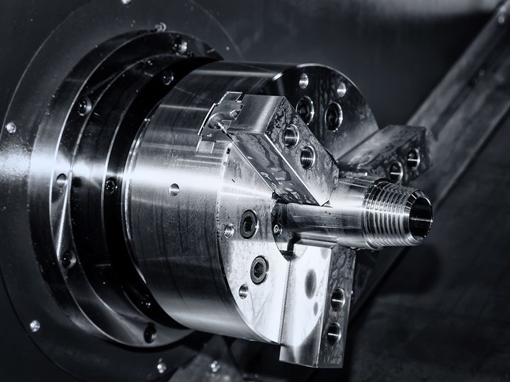
Photo credit: Getty Images
Using tee nuts requires one nut per jaw and securing each with two socket head cap screws. The serration pitch with this method is smaller, allowing a finer resolution for placement. But since the pitch is so small and there are many serrations in the master jaw, it can be difficult for operators to place all three jaws in the correct serration on the first try. As this process also requires tightening six screws, jaw placement can be tedious and time-consuming.
If the master jaws of the three-jaw chuck features fine serrations, and if each jaw is secured with two socket head cap screws then jaw mounting is likely taking longer than it should—especially for entry-level operators. The time is compounded if no one documents the jaw mounting position once the jaws are finally in the correct serration, operators will have to repeat this tedious task every time they run the job.
The positioning technique described below works best for dedicated jaws. These are jaws used for repeated jobs. After completing a production run, the dedicated jaws are set aside until the job is run again.
How to improve mounting accuracy
A low-cost, high-quality laser pointer can streamline the jaw mounting process. The fine beam of the laser pointer generates a small point that targets the location where the operator should mount each jaw. This keeps the operator from having to count serrations, and takes the guess-work out of jaw mounting.
That said, operators must also find a way to properly mount the laser pointer in the machine’s turret so that it points along the Z-axis toward the chuck. One method for mounting round laser pointers is to place them in the hole of a boring bar holder, though this requires operators to dedicate a turret station just for the laser pointer. In this situation, keeping the laser in the turret permanently should save time while cutting down on replacement and removal whenever your shop needs the laser. However, operators will need to protect the laser from coolant and debris generated by the program’s execution.
How to calibrate the laser
After mounting the laser pointer, operators must calibrate its location to the desired position of the jaws. One way of doing so would be to mount the set of jaws normally and with the jaws mounted, operators can monitor the X-axis register of the FANUC CNC “Machine” position page—or the equivalent on other manufacturers’ machines—to learn the X-axis location from the machine’s reference position.
For the best accuracy, operators should close the jaws (inward for external clamping) and turn on the laser pointer. Using the machine’s handwheel should bring the X-axis to the location where the laser beam is right on the jaw’s clamping surface. At this point, the X-axis register of the “Machine” position page should display the distance (in diameter) from the X-axis reference point. For our example, we will say the X-axis register shows a value of -8.3735 in. Add these commands to the CNC program to save the position for later use (and be sure to save this program to remember the added commands):
- .
- .
- N450 M30 (End of the machining program)
- N999 (Special sequence to position the laser pointer)
- G28 U0 (Move machine to X-axis reference position)
- U-8.3735 (Move laser pointer to jaw-mounting position)
- M30 (End of special sequence)
The next time the operator runs the job, they will scan to the N999 sequence and run the program from there. The machine will automatically bring the laser pointer into the jaw-mounting position and stop.
Alternatively, operators can calibrate the laser pointer by programming the beam to move to the desired jaw-mounting diameter before mounting the jaws. In this method, operators must determine the diameter at which the laser beam is pointing when it is at the X-axis reference position, then calculate the jaw-mounting diameter (with jaws in the clamped position). Operators will need to know the jaw stroke to ensure the jaws clamp on the part at the halfway point. With both diameters known, subtracting the jaw-mounting diameter from the reference-position diameter will provide the value of the U-word in the special sequence shown above (though the U-word will be negative).


Related Content

Inside a CNC-Machined Gothic Monastery in Wyoming
An inside look into the Carmelite Monks of Wyoming, who are combining centuries-old Gothic architectural principles with modern CNC machining to build a monastery in the mountains of Wyoming.
Read More
How to Determine the Currently Active Work Offset Number
Determining the currently active work offset number is practical when the program zero point is changing between workpieces in a production run.
Read More
Ballbar Testing Benefits Low-Volume Manufacturing
Thanks to ballbar testing with a Renishaw QC20-W, the Autodesk Technology Centers now have more confidence in their machine tools.
Read More
Orthopedic Event Discusses Manufacturing Strategies
At the seminar, representatives from multiple companies discussed strategies for making orthopedic devices accurately and efficiently.
Read MoreRead Next

Why Was This Block 3D Printed? To Help With Machining
This manufacturer making medical implants through additive manufacturing simplifies the machining by 3D printing the workholding fixture along with the parts.
Read More
T Codes Simplify Tool Length Confirmation Process
CNC users can program custom macros and T codes to ensure cutting tools are the proper length for tool length compensation in machining centers.
Read More
5 Tips for Selecting the Optimal Spindle Range
Learn how to select the appropriate spindle range and ensure that your CNC machining center or turning center is running an optimized cycle.
Read More