
Scanning For Process Improvements
A coordinate measuring machine with a constant-contact scanning probe makes it possible to get better, more complete information about workpiece features, especially contours. Two shops talk about how this information helps streamline their production processes.

Share


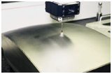
Figure 2. This is one of the punches Faith manufactures for customers who form the thin metal masks found in every color CRT screen.
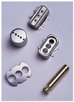
Figure 5. This is just a few of the small high precision parts mass-produced by Premium Allied Tool. Premium has a reputation for seeking difficult parts that other suppliers are reluctant to tackle.

Figure 3. Faith has developed some innovative machining techniques to produce contoured surfaces on a mask punch, such as grinding the surface on a machining center. Scanning these surfaces on the CMM verifies and monitors the effectiveness of these techniques.
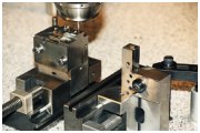
Figure 7. A punch and die set used to form contact spring is fixtured on the CMM for inspection. The forming die is being scanned while the mating punch waits its turn to the right.
Figure 4. A printout like this shows where a punch surface has low and high spots. By manipulating the tolerance band so there is no material out of spec on the low side of the tolerance, out-of-spec areas on the high side can be identified. These areas appear in red. This is the only material the toolmaker has to remove while stoning to bring the entire surface within tolerance.
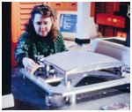
Figure 1. At Faith Tool & Die's newest CMM, Mary Wood adjusts the fixture holding a metal mask for a CRT screen. The probe touching the mask will scan its contour by collecting thousands of data points as it travels across the workpiece in constant contact with the surface.
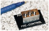
Figure 6. This gage is typical of those used to inspect high precision parts on the shop floor at Premium.
And both companies are benefitting from coordinate measuring machines (CMMs) equipped with scanning probes. A scanning probe literally stays in touch with the workpiece surface, following the contour as it goes and collecting thousands of data points along the way. This higher level of information helps these two Owensboro shops improve die making, die maintenance, and even gage calibration.
Premium Allied Tool, the larger of the two companies, is heavily involved in mass producing many of the small, very precise components used to assemble the "gun" that shoots beams of electrons onto the florescent back surface of a cathode ray tube.


Faith Tool & Die, acquired in 1984 by the parties who own Premium, is involved in larger components for TV screens. For example, behind the curved glass panel at the front of every color TV tube and computer monitor is a thin sheet of metal full of very small holes. This mask, as it is called, makes the projected video image sharper and brighter. Faith manufactures the punch and pad sets that are used to form these metal masks. Mary Wood, the CMM operator pictured in Figure 1 (at right), is measuring one of those masks.
The thin metal mask is being measured on a CMM equipped with a scanning probe from Electronic Measuring Devices, Inc. (EMD) of Budd Lake, New Jersey. The scanning probe, unlike a touch-trigger probe typically found on a CMM, captures a continuous stream of data points as the stylus moves along the surface of a workpiece. The probe is in constant contact with the workpiece surface. Data points are recorded at a predetermined frequency—so many per inch or millimeter—depending on the size and complexity of the surface. The sidebar (at the bottom of this article) takes a look inside the probe.
Using a scanning probe is often a better way of measuring a part surface and many times the only way to measure certain features. For Faith Tool & Die, measuring surfaces with a scanning probe helps to streamline machining procedures, reduce bench work, deliver finished work more quickly, but most of all, it ensures that workpieces are more accurate, that is, closer to the ideal conditions that lead to best performance.
This is true at Premium Allied Tool, too, but their experience brings out additional aspects of a scanning probe's usefulness. Some of Premium's routine uses of the scanning probe, for example, show how it has valuable day-to-day applications that conventional wisdom might not recognize.
Punches That Hit The Mark
Producing contoured surfaces that are true to the specified geometry and compliant with surface finish specifications is a challenge for many segments of the metalworking industry, but especially so among die and mold builders.
The scanning probe on a CMM helps these Owensboro companies meet this challenge. This is easiest to see at Faith Tool & Die.
A good example is the punch and pad set used to form the TV masks. A typical punch is shown in Figure 2 (at left). A customer will use this punch to press-form the mask from a sheet of metal 0.004 to 0.009 inch thick. Tiny apertures are photochemically etched into this metal, removing 40 to 60 percent of its volume. The punch and pad not only give the metal the readily-identifiable TV screen shape and curve, but they also form a raised stiffening bead around the periphery of the mask. This long, narrow crimp in the material makes it resist bending so that the mask holds its shape during handling.
Starting with a block of pre-hardened H13 steel alloy, the punch is rough-machined on one of the shop's machining centers. Machining in three axes with a ballnose end mill takes the die to within 0.001 inch or so of the defined geometry. However, Faith has set an internal goal of machining the contoured surface of the punch to within 0.0005 inch. To meet this goal, the shop uses an unusual grinding process as shown in Figure 3 (below, right).
At this point, the punch is then scanned on a Starrett Model RGSC 4040-24 CMM using a scanning probe system provided by Electronic Measuring Devices. This is a matter of directing the CMM to move the probe side to side across the punch in fairly wide (about one inch) stepovers, recording points every 0.100 inch. The same pattern is repeated from the top to bottom of the punch.
For a scanning probe to collect data efficiently, it must be supported by powerful CMM software. EMD's scanning probe system includes its Sceptre software, which provides the software tools for controlling the CMM and recording the large volume of scanned data points. According to Lewis Boteler, who heads up Faith's inspection department, this software facilitates both of these key functions. "In a nutshell, the software lets us command the CMM to start scanning at one point on the workpiece surface and stop scanning at another point. We don't have to define the shape to create a program to measure it. And we can scan multiple shapes without changing the program. With the Sceptre software, the CMM scans the part and then tells us its shape in X, Y and Z coordinates."
Seeing Through The Clouds
Scanning collects a large quantity of data, known as a "point cloud" because the density of the points makes displays of this raw data on a computer screen look like a hazy, nebulous cluster. The Sceptre software organizes this point cloud into an X, Y, Z format that represents the scanned surface. In this format, the data can be used for further analysis within the Sceptre software or it can pass the data to other systems in an exchangeable format such as IGES.
Faith follows this second option. To interpret the scanned data and create a mathematical model of the surface that has been scanned, its engineering department uses an analysis software package, called IQBestFit, which the company acquired from Starrett when the new CMM was installed two years ago. With this software, Faith's manufacturing engineers can compare the scanned surface of the punch with the specified geometry as defined in a CAD file.
The software positions the point cloud by rotating it about the X, Y and Z axes until points are most evenly distributed over the NURBS-defined surface from the corresponding CAD file. It then calculates the deviation between the point cloud and the NURBS surface and ascertains that any deviation is within the specified tolerance band. At this point, the punch is returned to the milling department for machining the groove that forms the reinforcing bead on the mask. This step is performed with a 1/16-inch or smaller ballnose end mill.
Afterward, the punch returns to the CMM and is re-scanned. The new data is analyzed again by Engineering to verify the depth and location of the bead groove. This information is compared to the size and location of the raised bead on the mating pad to check the fit of the bead.
"By researching the patterns of the deviations and finding causes, we can improve the quality of CNC milling," says Susan Dotson, a designer/project coordinator at Faith. "With CNC producing parts that are well within specifications, the toolmaker can now concentrate on achieving the desired surface finish." See Figure 4 (at right).
"As far as altering the geometry in the hand polishing step, scanning the punch afterward verifies that we have stayed within the specified tolerances," Mrs. Dotson adds. "Also, by studying the data between mating components, we can predict how the components will fit together. This helps the toolmaker when going to the spotting press."
A Light Touch
The scanned data plays one other significant role in streamlining production. Sample masks are produced to test the punch and pad set and these samples are also scanned on the CMM.
"We need to verify the surface of the mask to be sure the springback was calculated correctly when designing the punch and pad," explains Mr. Boteler. "The software determines that in the same way it compares surface models for machining error. Springback is slight—a few percentage points—so the precision of the CMM is needed to capture that small a change. By measuring the mask, best-fit analysis can show us precisely how to adjust the contour on the punch and pad to correct springback in the rare times that is necessary."
Measuring material this delicate would be virtually impossible without the scanning probe. The probe's control software allows the contact pressure to be adjusted so that it does not deflect the surface of the mask. In this case, probe pressure is set at 7 to 10 grams. This pressure will be maintained consistently across the surface of the workpiece.
Gage Calibration
On the other side of town, Premium Allied Tool also makes good use of the scanning capability with which its newest CMM is equipped. This CMM, a Starrett Criterion, has the same scanning probe system from EMD that Faith uses. Whereas Faith builds tooling for its own production applications and for outside customers as a job shop, Premium builds tooling strictly for its own production work.
This production work is remarkably extensive. The company is the leading world-wide producer of certain CRT components, the mainstay of its business. These and numerous other high precision parts (see Figure 5, at left) keep its banks of production machines busy around the clock. These machines include high-speed transfer presses, multi-spindle screw machines, and four-slide machines.
To support this operation, the scanning CMM serves two main functions. It calibrates all of the critical gages used on the shop floor to monitor production quality. And it helps in the manufacturing and maintenance of tooling, not unlike the way Faith Tool & Die uses its scanning CMM as discussed above.
The first of these functions is especially important at Premium because gages play a key role in process monitoring. Stan McKay, the toolmaker assigned to the CMM here, estimates that 70 percent of the work of this instrument is devoted to calibrating gages. About 60 pin gages similar to the one shown in Figure 6 (below, right) cross the CMM a week.
This gage is representative of those used to inspect production workpieces. Many of these parts fall into families in which an array of three holes is a common characteristic. On many of the shop's production machines, samples for checking are gathered with parts catchers that automatically swing under the finished part chutes at timed intervals to catch a random selection. Each sample part is checked by placing it on the gage. Holes on a good part will fit snugly on the three pins of the gage.
"These are high precision gages with tolerances in the millionths," Mr. McKay points out. Tolerance on pin diameters is +0.00002, -0.0 inch. Location of the pins must be within ±0.000025 inch of nominal. Gages are returned to the inspection lab for recalibration at regular intervals—every three months for gages with pins 0.050 inch or smaller, every six months for larger sizes.
So why a scanning probe for this operation? "To begin with, the pins on
some gages can as small as 0.015 inch," Mr. McKay points out. "A conventional touch probe could cause deflection and give us false readings, whereas the scanning probe allows us to set the probe's measuring force." (The smallest pins are scanned at 10 grams, for example)
"The next reason is accuracy," Mr. McKay continues. "We use this CMM as a precision comparator. For each size pin on the gages, we have a corresponding master pin that is traceable to national standards in Washington. We scan the master pin and compare it to the nominal. This gives an offset that reflects any environmental influences on the CMM.
"Then we scan each pin on the gage three times and average the results. Averaging checks the repeatability of the machine. Next, we add or subtract the offset and check to see that the result is within the specified tolerance band." As Mr. McKay sums up, "This procedure gives us diameter and location of the pins to a repeatability of 3 to 5 millionths." (For reference, 3 millionths of an inch—0.000003 inch—is a thousand times smaller than the average human hair.)
The CMM's software, which is the same Sceptre software from EMD that Faith uses, is also an important part of gage calibration at Premium. "This software lets us create a canned routine that automates scanning of the pins," explains Mr. McKay. The software prompts the user for information about the nominal dimensions of the pins and their relative location. Scanning parameters, such point density and scanning speed, are also entered. About twelve questions have to answered to program the CMM to scan a three-pin gage.
"After entering this data," Mr. McKay recounts, "we use the probe to collect three points on the top surface of the gage to establish a reference plane. Then we position the probe close to the first pin and begin scanning in the automated mode."
To scan the pins, Mr. McKay uses a stylus with a 1.0 mm tip, recording points every 10 micron (0.01 mm). It takes approximately 40 to 50 minutes to complete the recalibration of each gage. Smaller pin sizes take longer because the speed of the scanning probe must be slowed down considerably to stay in contact with the pin during scanning.
After scanning, data is analyzed and used to generate a report that gives expected and actual deviation, the tolerance band, and a pass/fail judgment for each critical feature. This report is reviewed by the engineering department to verify that the gage has been approved for production monitoring or final inspection. Upon approval, the gage is made available for active duty in the plant.
Production Tooling
Production tooling also benefits from the scanning probe. The big difference between what Premium does compared to its sister company is that the tooling is much smaller. The forming tool shown in Figure 7 (at left) is typical. This tool forms an inch-long stainless steel contact spring. This part, with one end shaped a bit like a shallow dipper, makes an electrical contact inside the neck glass at the rear of a CRT tube.
When a tool for forming a part like this is being built, it follows the same back-and-forth itinerary between shop floor and inspection department that the mask punch follows as described earlier. Scanning the contour of the punch and die gives the toolmaker exactly the information needed to get a virtually perfect match between the shape of the tool and the specified geometry, in a minimum number of steps. A final scan captures the results of any handwork for later reference.
"Debugging" of a new tool includes scanning test parts that it has produced. Test parts may reveal that further clearance adjustments are needed to reflect behavior or thickness of the raw material.
Periodically, tooling returns to the scanning CMM to be checked for wear. Comparing new scanned data with the original quickly reveals the extent and location of any wear conditions and whether the tool can be returned to production or must be reworked or replaced.
Scanning The Horizon
Jim Day, the president of both Premium Allied Tool and Faith Tool & Die, stresses the importance of enhanced inspection capabilities as an integral part of process improvement. "For most of the history of these two companies, growth has been tied to CRT technology. We went after the parts that nobody else wanted to make and we demonstrated the ability to make them better than anyone else could. But flat screen video technology appears to be the wave of the future. That means most of the parts we make now will no longer be part of the growth curve in this industry.
"To succeed in new opportunities, we need to be able to streamline production strategies, no matter what kind of part we make for our customers. That's why using measurement tools to help us reduce the number of production steps as well as to minimize each step is so important in the short term and long term. There's an immediate payback in better tooling completed in less time, for example, but being ready to apply the same sort of responsiveness to new manufacturing challenges—that's what makes it worthwhile." MMS
For more information, visit Electronic Measuring Devices' Showroom.
For more information about coordinate measuring machines, visit Starrett's Showroom.
To contact Premium Allied Tool, call (502) 729-4242. To contact Faith Tool & Die, call (502) 683-6251.


.png;maxWidth=300;quality=90;format=webp)
Related Content

Measuring Torque, Thrust Force for Smart Drilling Operations
To monitor drilling operations for smart manufacturing solutions, torque and thrust force can be measured.
Read More
AI Creates CAD Files From Scan Data
While 3D visual scanners are useful, converting a visual scan to a usable CAD file can be a time-consuming process. With generative AI, it may be much simpler and faster.
Read More
4 Ways to Establish Machine Accuracy
Understanding all the things that contribute to a machine’s full potential accuracy will inform what to prioritize when fine-tuning the machine.
Read More
A Balancing Act for Differential Gaging
Differential gaging measures using two devices, which has advantages over standard, comparative measurements using a single sensing head. These include the ability to measure size without regard to position.
Read More