
Properly Reading Dial Indicators
Dial indicators provide useful readings about tolerance ranges at a glance — but new users need to know how to set up these indicators before using them.

Share


Dial indicators have been around since the early 1900s, and, while digital indicators may be gathering more attention recently, dial indicators are unlikely to ride off into the sunset any time soon. This older tool's long-term popularity is well-earned. Dial indicators offer good resolution at a low cost, but that is not the main reason people still use them, especially some of the more experienced users. I am one of those experienced users still wearing a watch with an analog dial because the analog dial gives me a sense of where I’m at. In the analog world, I know at a glance if I am approaching the time needed and whether I have lots of time or just a little. The same analog benefits apply to dial indicators.
Beyond providing easy-to-read quantitative measurements, dial indicators give users a comparative sense that their parts are in the right ballpark. The user can simply see if the indicator’s needle is within tolerance bands or, simpler still, lies within red sections highlighted on the dial. No interpretation is necessary. Not every result may read like a home run, but as long as it’s not in the outfield, it scores as a good part.


Dial indicators vary widely in type, size and range. All translate variations (through internal movement of a plunger) into dial readings. Some will indicate dimensional variations as small as 0.00005". Therefore, these sensitive mechanisms must be handled with the same devoted care as other precision equipment.
There is always a fresh set of users who may be seeing a dial indicator for the first time. Even though these indicators are relatively basic tools, new users require some knowledge to properly read them.
Dial indicators — also known as dial gages, clocks, comparators or just indicators — are widely used as basic gages for measuring linear dimensions. A dial indicator is useless by itself and needs to be attached to a fixed base or a stand so that the tip of the spindle is at a specific height against either a master or reference part. An operator then lifts the spindle with a lever, slides the part to be measured under the spindle and lowers the spindle back down. If the part length is different from the reference, the operator will see the deviation on the indicator's dial. Seeing this part deviation is what reading the indicator is all about.
Dial indicators come in various sizes, ranges and resolutions. They can have balanced or continuous dials, and some types can even work backward based on the particular application. All these options are available because the goal for the indicator is to allow the user to read it as easily as possible without requiring too much interpretation.
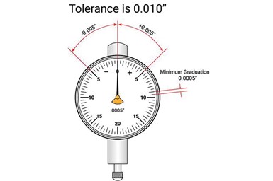
Returning to the analog watch comparison, with this dial configuration, users will need to adjust the gaging application and indicator to have the master zero setting point at the 12 o’clock position or “0” on the dial. Most dial indicators are then used in a comparative mode using a balanced dial, with minus (-) readings on the left of 0 and plus (+) readings to the right of 0. The goal is that the plus and minus tolerances are in the range of the 10 and 2 o’clock positions on the dial. There are also large-approach and over-tolerance ranges to see the work coming into tolerance, similar to the analog feature on my dial watch mentioned above. At the 10-2 position, about 20% of the dial is large enough to easily view the intolerance position.
Now, most dial indicators will have more than one revolution of the hand, usually at least 2.5 revolutions, and there may be a small hand on the dial counting the revolutions to prevent user errors. But in the end, the comparative reading balancing the part tolerance around zero on the indicator is what the user is looking for.
The above image shows an example of a balance dial with 0 at the 12 o’clock position. The “-” sign to the left of “0” is signifying a smaller dimension, while the “+” sign to the right signifies a larger dimension. To obtain the actual deviation of the part compared to the master, simply count the number of graduations (minimum grad values) to obtain the plus or minus deviation.
As illustrated, there are small and large grad marks (similar to minute grads on a watch) that help in counting the grads. However, in the analog use of the indicator, as long as the hand is within the tolerance limit, that’s really all that counts.


Related Content

A Balancing Act for Differential Gaging
Differential gaging measures using two devices, which has advantages over standard, comparative measurements using a single sensing head. These include the ability to measure size without regard to position.
Read More
4 Ways to Establish Machine Accuracy
Understanding all the things that contribute to a machine’s full potential accuracy will inform what to prioritize when fine-tuning the machine.
Read More
AI Creates CAD Files From Scan Data
While 3D visual scanners are useful, converting a visual scan to a usable CAD file can be a time-consuming process. With generative AI, it may be much simpler and faster.
Read More
A 100-Year-Old Measurement Tool That is Still Used Today
The reed mechanism was a breakthrough in high-precision measurement and is still used today for sub-micron or even nanometer resolution applications.
Read MoreRead Next

What to Know About Decoding Surface Finish Gages and Parameters
Long-wavelength waviness and short-wavelength roughness require a wide variety of instruments and parameters for proper measurement — and lower numbers aren’t always better.
Read More
Confirming Dimensional Accuracy of a Precision Ball
A single diameter isn’t the only measurement parameter that can be used to ensure accuracy.
Read More
Choose the Correct ID/OD Gage for the Task
Benchtop and portable comparator gages each have their place, but the differences are more than surface deep.
Read More