
The Right Start For A Fine Finish
Developers of CAM software have introduced many programming features for the initial removal of excess stock prior to finishing operations. By preparing the workpiece surface for more effective finishing, these roughing routines often determine how efficiently a CNC machining center can perform.

Share


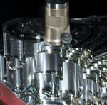
Ingersoll Cutting Tools (Rockford, Illinois) provided this photo showing one of its new Button Top-On cutters approaching a workpiece roughed with an Ingersoll Punch-In cutting tool. As cutting tool manufacturers introduce improved tools for roughing, CAM software developers are creating new programming features to take advantage of these tools.
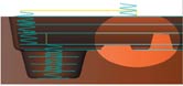
Fig. 4—Z-level roughing mills away a pocket or cavity layer by layer as the cutting tool steps down from the top. Mastercam demonstrates the efficiency gained by having a layer match the top surface of flat plateaus or bosses within the cavity.
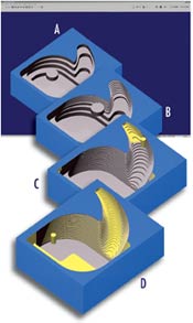
Fig. 3—This sequence shows how SurfCAM's step reduction milling feature works. In A, a large roughing tool taking deep stepdowns leaves behind wide steps. Before switching to a smaller tool, the first tool returns and remachines the steps with shallower stepdowns in B. After changing to a small tool in C, new tool paths repeat the stepdown process, creating a another pattern of steps. In C, the small tool also returns to further reduce the height and width of the steps with an even finer series of stepdowns, bringing the workpiece much nearer to the net shape of the desired geometry.
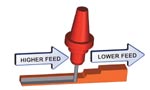
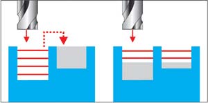
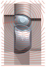
Fig. 7—In Delcam's PowerMill, a feature called Race Line Machining gives roughing passes a smoother, gentler flow across the workpiece.
It would be terribly inefficient to begin machining a workpiece with the same techniques required to finish it. Because the last passes of the cutting tool determine the workpiece's final shape and surface quality, the applicable machining parameters are set accordingly—light cuts perhaps, or a small diameter tool for details, or conservative acceleration and deceleration, for example.
To get to the stage where these techniques are practical, most machining processes start therefore with some method of roughing. It is called roughing for good reason. Roughing may initially create a shape that only roughly approximates the final desired shape. Roughing often leaves behind a rough surface characterized by scallops, steps or ridges. Roughing also implies rougher (as in "more aggressive") machining parameters, with faster speeds, deeper feeds and larger tools.


However, there is nothing rough or crude about the strategic importance of roughing. The essential goal of roughing is to remove material as efficiently and as safely as possible yet still leave stock conditions that maximize the effectiveness of finishing operations. Because finishing operations are usually constrained by specified requirements, roughing may represent the only opportunity for the planner or programmer to find a machining advantage. The choice of roughing methods seeks not only to optimize removal of excess material but also to optimize finishing operations, thereby influencing the entire machining process. Roughing counts twice.
The strategic value of roughing has not been lost on the developers of CAM software. Advances in programming features for roughing on a CNC machining center enable the programmer to reduce programming time as well as reduce machining time when the program is executed. Advances in roughing features also differentiate one CAM package from another, making these features a strong part of the developer's strategy for enhancing customer appeal. So both end users and developers have a stake in their success with programmed roughing routines.
This article takes a look at the nature of these roughing routines and highlights some of the more representative or innovative roughing features available in today's CAM packages. These observations are based on an informal sampling of the market and are not meant to compare one system to another. The purpose is to stress the strategic importance of roughing and point out how much attention it is getting from developers. The next time you are shopping for CAM software, make sure you take a close look at the roughing features it offers. Just as a machining cycle usually starts with roughing, evaluating CAM software can, too.
Block Or Not A Block
Although the goal of roughing is to prepare for finishing operations, how the workpiece starts out is a major consideration. Software tools to program the roughing of a mold half that starts out as a block of steel will differ from the software tools to program the roughing of a compressor part that starts out as casting in a large production run.
The roughing features found in the EdgeCAM family of CAM software from Pathtrace Systems Inc. (Southfield, Michigan) show how roughing is very different whether you start with a solid block or a pre-shaped workpiece such as a casting or forging. When starting with a solid block of material, how the tool enters the cut is especially important. EdgeCAM has a "region detection" capability that automatically classifies various regions to be removed and selects the most appropriate approach to tool entry.
For example, portions of the workpiece open to one or more sides will be entered differently than closed areas such as pockets or pockets with bosses. Figure 1 illustrates lead-in styles to suit different types of regions. The software selects the best approach in this order of preference:
- Plunge from outside the stock area
- Single ramp move
- Helical ramp
- Zigzag ramp
- Profile ramp following contour
- Plunge into material (when a capable tool is provided)
Region detection allows the software to sequence tool paths in the most efficient order: by removing regions that can be machined most efficiently first, then following with less efficient tool paths without superfluous passes in regions previously removed.
The company explains that this level of automation is valuable in applications starting with solid blocks because they typically involve small batches or unique pieces such as prototypes, molds or die components. Automation reduces programming time while the underlying algorithms generate tool paths that protect the tool and the workpiece.
Applications involving pre-shaped material, in contrast, are generally for mid- to high-volume production. Minimal cycle time, not minimal programming time, is the priority. It is important to optimize roughing passes, the company says, because savings in cycle time accumulate significantly over the production run. In keeping with this philosophy, roughing features must emphasize flexibility in roughing options.
For example, the emphasis shifts to detecting the stock in order to generate tool paths that avoid cutting air. Figure 2 illustrates this concept. EdgeCAM allows the programmer to apply a stock offset based on the shape plus the casting tolerance, creating a safe zone that accommodates any uneven stock conditions that might be encountered in the first pass.
Where applicable, the software also allows the programmer to select a "high speed links" option that generates tool paths with no sharp corners. This option programs the cutter to move in smooth arcing paths yet not leave uncut areas even when stepovers exceed 50 percent of the tool's diameter. Tool entry options are also tailored for efficient cutting.
Catching Some Zs
Many CAM packages offer some type of Z-level roughing. This technique automatically slices a volume to be removed into layers representing the step-by-step descent of the cutter in the Z axis. Each successive layer is removed by tool paths in the X-Y plane, as the Z depth remains constant in that layer. Using a large cutter at its full depth of cut maximizes the metal removal rate. After each layer has been milled away, the rest of the material needing to be removed forms terraced steps where walls of cavities or sides of protrusions are sloped.
Typically, the rest of the material is roughed away using smaller and smaller cutters in progressively shallower Z-level slices, leaving smaller and smaller steps on sloped surfaces until finish machining conditions are reached. That is why the terms "rest machining" or "rest roughing" are used to describe the roughing feature that calculates these uncut areas of material and generates tool paths to "clean them up."
To program rest machining routines automatically is a demanding challenge for software developers, and the efficiency of this feature varies from CAM system to CAM system. Yet CAM developers have not been napping when it comes to introducing new options to further automate and enhance Z-level roughing and rest machining.
For example, Surfware, Inc. (Westlake Village, California) has developed what it calls step reduction milling for its SurfCAM software. The concept is to complete Z-level roughing with the first tool as expected. Instead of proceeding with a smaller tool to remove the large steps left behind by the first cutter, however, this process returns with the original cutter to "clean up after itself." Step reduction milling programs a new series of constant Z-level passes, allowing the larger tool to reduce the width and depth of the steps, as shown in Figure 3, above, right. This process takes advantage of the greater machining efficiency the larger tool offers compared to the small tools that follow.
This feature has the intelligence to set the depth of cleanup passes according to the maximum depth of cut allowable for the next smaller tool. This ensures that the reduced steps are uniform and appropriate for the smaller cutter. This results in the largest tool possible removing as much material as possible, yet each successive tool cuts at its most efficient parameters. According to the company, the resulting CNC program runs significantly faster and quieter, with less stress on the machine and cutting tools.
Step reduction milling reduces programming time by allowing the programmer to enter a complete list of roughing tools, and then to push a button, letting the software calculate the entire roughing sequence with little or no manual intervention.
Other developers have new features to give users more control, more automation and more flexibility in established techniques such as Z-level or rest machining. To mention a few, Pathtrace's EdgeCAM has its own step reduction option that programs "intermediate steps" for the cutter to follow after its initial Z-level routine. These intermediate steps are cut from the bottom up to maximize the amount of material the cutter can remove radially as it moves up to the next intermediate step.
Teksoft CAD/CAM Systems (Scottsdale, Arizona) offers a "slice roughing" technique that programs the cutter to follow the contour of the sidewall or slope at the end and beginning of each stroke. This eliminates the leftover steps altogether. Total Z-level roughing cycle time increases slightly, but the leftover material for rest machining is greatly reduced.
Mastercam software from CNC Software (Tolland, Connecticut), among others, has added "critical depth" control for its versions of Z-level roughing. This option automatically inserts a Z-level layer to coincide with the tops of plateaus or other flats on bosses within a pocket, as shown in Figure 4, above left.
Taking The Plunge
Like Z-level roughing, plunge roughing is an increasingly popular roughing technique that is not new but has been enhanced by CAM developers, mainly in the interest of giving programmers more flexibility and control. Plunge roughing is essentially the process of removing material by plunging a series of holes with overlapping diameters. Twist drills were originally used, but special end cutting plunging tools are commonly used today.
Plunge roughing takes advantage of the downward thrust of the Z axis, which is usually the strongest and most stable axis on a machining center. Likewise, plunge roughing exploits the inherent efficiency of drilling action as a material removal method. Plunge roughing is especially effective when a large diameter tool is roughing relatively shallow pockets.
Teksoft's ProCAM II has plunge roughing features that typify recent enhancements to this technique. For example, to make plunge roughing more effective in deep cavities, the programmer can apply a stop-and-repeat cycle for each plunge, allowing the tool to retract for chip clearance. Variable plunge depth can be set automatically to rough cavities with contoured floors as in mold work. See Figure 5.
Another option automatically calculates and identifies the location of pilot holes that must be predrilled when programming for tools that are not center drilling. The resulting program machines all of the pilot holes as a separate operation preceding the plunge roughing operation.
Giving more control over the pattern of plunge locations is another way CAM software makes plunge roughing more effective. Typically, plunge roughing features apply parallel rows of holes in a grid that covers the area to be removed without violating the area's boundaries. This process is very efficient but does not always create the most advantageous cutting conditions.
"Custom plunge roughing," a new feature in Mastercam, enables the programmer to define any plunge pattern for special situations. Generally, these patterns follow the natural shape of the workpiece. Figure 6 shows how a circular pattern spiraling out from the center of a wheel-shaped workpiece makes sure that chips always fall away from the cutting zone. Such considerations are especially valuable in production runs.
Tool Protection
A prevalent theme in emerging roughing strategies is protecting the cutting tool. The goal of roughing is to remove a lot of material as quickly as possible but not at the risk of damage to the cutter or the machine itself.
The latest version of PowerMill from Delcam International (Windsor, Ontario) includes several enhancements for "high-efficiency roughing," and these enhancements emphasize tool paths that maintain favorable cutting conditions. For example, Delcam has introduced an option for what it calls Race Line Machining, for which the company has a patent pending. With this option, the roughing passes are progressively smoothed out as tool paths move further from the main form, as seen in Figure 7, below left. The concept is similar to the steering of a racecar negotiating an S curve, where the driver naturally takes a path that makes the smoothest, least curvy route.
According to developers, the benefits of Race Line Machining are:
- Less deceleration into bends in the tool path,
- The fewest sudden changes in tool direction,
- Faster machining,
- Extended cutter life, and
- Less stress on the machine tool.
- Figure 7, at left illustrates the concept.
Among other roughing developments in PowerMill is a "model edge offsetting" option. This feature generates the tool paths for each layer (offset) in Z-level roughing by taking into account the shape of the geometry at each level. The tool path is made to work from the edge of the geometry outward to maintain a climb milling condition to the greatest extent possible. This method maintains a constant tool load and uniform chip production, keeps the cut direction constant, avoids machining small or thin-walled uncut portions, and minimizes full width cuts.
Torchoidal Roughing
Roughing out slots or channel-shaped cavities in hard metal is a special case worth mentioning. Delcam, along with other CAM developers, has added torchoidal machining as a roughing technique of particular value in this situation. In essence, the cutting tool makes a series of short loops as it moves forward. This technique avoids engaging the full width of the cutting tool by generating tool paths that progressively shave material from the block in a circular motion. In PowerMill, this option automatically adjusts the tool path to maintain efficient and safe machining at any direction changes in the slot.
Gibbs and Associates (Moorpark, California), has recently incorporated a torchoidal machining tool path capability into its GibbsCAM application. The company finds that torchoidal machining is extremely useful in machining high strength materials or high speed machining, and it can also be used for various roughing situations such as pocketing. See Figure 8.
Torchoidal machining has a number of advantages. Considering the general dynamics of machining, torchoidal machining's circular motion has the tool cutting material on the forward motion in each loop. The backward motion in each loop allows cooling of the tool and free chip removal. When machining high strength materials or when taking an aggressive cut, this forward stroke loading of the tool balanced with a cooling/chip removal arc creates optimum machining conditions. In addition, because the torchoidal tool path is comprised entirely of circular motions, there are no abrupt directional changes—an ideal situation for both high speed roughing and finishing.
Smoothing The Way To New Roughing Features
Certainly there are noteworthy developments in roughing that this article overlooks. Certainly there are noteworthy developments in roughing that are as of yet unannounced but are sure to create a stir when they appear.
A source at Mastercam had an interesting observation about how end users will acquire new roughing features or any new software enhancement for that matter. Rather than wait to release these new features until the next complete version of the software is available, developers are increasingly likely to distribute new features to end users as upgrades or plug-ins downloadable from the developer's Web site on the Internet.
Given the strategic value that roughing commands, we can expect the appearance of new roughing techniques and options to continue steadily. Likewise, the eagerness of programmers to get their hands on these new features is not likely to diminish.


Related Content

10 Robotic Solutions You Can Find at IMTS 2026
Discover how today’s robots and cobots are making it easier than ever to automate tasks, free up skilled workers, and run machines unattended – even in small and midsized shops.
Read More
Cutting Part Programming Times Through AI
CAM Assist cuts repetition from part programming — early users say it cuts tribal knowledge and could be a useful tool for training new programmers.
Read More
Shop Reclaims 10,000 Square Feet with Inventory Management System
Intech Athens’ inventory management system, which includes vertical lift modules from Kardex Remstar and tool management software from ZOLLER, has saved the company time, space and money.
Read More
Can AI Replace Programmers? Writers Face a Similar Question
The answer is the same in both cases. Artificial intelligence performs sophisticated tasks, but falls short of delivering on the fullness of what the work entails.
Read More