Machining 101: What Are Coordinate Measuring Machines?
Optimized bases, drives, probes, software and more make coordinate measuring machines the most accurate tools for measuring part dimensions.

Share


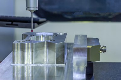
A coordinate measuring machine (CMM) is a measurement tool that consists of a motion system, a probing system, a computer and measurement software.
The frames and base of CMMs must be secure from vibration and thermally induced variations. Although aluminum and granite frames are both common, granite’s superior thermal stability and vibration damping makes it the most effective option. The working surfaces of granite surface plates are also precision-lapped, enhancing their compatibility with common air bearings.


Air bearings have largely replaced roller-bearing systems. These newer bearings do not wear because they are non-contact and use no moving parts that would otherwise create noise or vibration. Porous graphite and aluminum are both common bearing materials, but porous graphite uses an air gap of 0.0002 inch as opposed to conventional, orificed aluminum’s much-larger 0.001- to 0.003-inch air gap. As smaller gaps reduce increase rigidity and repeatability by limiting machines’ tendency to bounce on the air cushion, porous graphite tends to be the superior material.
CMMs also typically use glass or another type of reflective scale to measure the position of each axis within the machine’s movement range. When the reader head, which is attached to the moving member of the axis, moves across the surface of the scale, a pulse generates and instantly converts to a digital reading. The finer the marks are on the scale, the finer the resolution of this reading will be.
Distributed numerical control (DNC) CMMs should minimize backlash in the drive system, as with counterintuitively named “friction drives.” These drives pair a direct shaft drive with a precision drive band. By eliminating the reciprocating shaft found in traditional screw drives, friction drives eliminate a major source of vibration and (ironically) operate with very low amounts of friction.
CMM Probe Characteristics
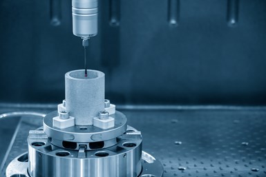
Probe heads mount into the ram (or arm) of the CMM. The trigger mechanism may also be built into the head, with the stylus mounted directly to the head or with a stylus extension extending the head’s reach. Extensions are particularly common on smaller machines to increase stylus reach and improve the machine’s maximum measuring volume.
Probes for CMM machines can use various trigger mechanisms. Touch trigger probes, analogue probes, and piezo electric probes contact the part, while optical and laser probes do not.
Nonarticulating probe heads measure only straight down, and are mostly used for measuring machined or stamped impressions in flat sheet metal or similar applications. These probe heads are usable with both manual and DNC machines.
Articulating probe heads allow the probe to point in many different directions and enable measurement of parts’ back sides. Some manufacturers use two angles to control the probe. The first angle determines the number of degrees the probe deviates from straight down, while the second angle determines — in increments of 7.5 or 15 degrees — the direction the probe points in the horizontal plane. These types of probe heads are also usable with both manual and DNC machines.
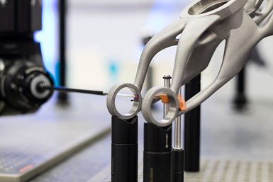
Trends toward smaller components and tighter tolerances require users to collect and analyze more data points. Scanning probes, which automatically collect enough data points to accurately define the workpiece’s shape, meet this need. CMMs compatible with scanning probes were prohibitively expensive in their early days, but technology has advanced enough over the past few decades to make scanning-capable CMMs more affordable. Modern scanning probes combine optics, video and laser technologies into devices that rapidly scan complex shapes and surfaces, with paired mathematical engines analyzing the data.
Evaluating Accuracy
CMM accuracy is often listed in a notation such as “2.3 + L/600.” This notation follows ISO 10360-2, and comes from the formula E = A + L (1 ÷ K). In this instance, E is the accuracy as read on the Y-axis of a graph; A is the constant equal to E if the length of travel is 0; L is the length of travel of the measuring probe; and 1 ÷ K is a constant and the slope of the straight-line.
Determining the constants requires a specific testing process. Seven configurations (lines of different lengths and orientations) are established within the X, Y and Z travel volume of the CMM. Each configuration has five target points, and the machine moves to each target point three times. This creates 105 total readings.
The absolute differences between the target points and the actual CMM readings are plotted on a graph where the X-axis is the length of travel between points, and the Y-axis is the “error of indication,” or, accuracy. Machine builders determine accuracy by fitting a line over all 105 points and finding the slope, K. A is where this line crosses the Y-axis.
Manufacturers usually present formulas with constants A and K already inserted. Thus, in the opening example, 2.3 + L/600, A is 2.3 and K is 600.
CMMs on the Shop Floor
The CMM collects data faster than manual measuring instruments, and offers great flexibility and operational swiftness in the right hands.
Historically, however, CMMs had drawbacks that prevented their use as shop-floor inspection devices.
The demand for extremely close-tolerance production has spurred change in this regard, moving toward the integration of CMMs on shop floors. These measurement stations might be physically attached to a production line or integrated through a transfer device (like a cart, rail-driven vehicle or other conveyor).
By moving dimensional inspection closer to manufacturing operations, operators have much greater control over the process. Increased control reduces scrap and rework by reducing the probability of producing out-of-tolerance parts. Machine tool operators can usually carry out shopfloor CMM applications with the aid of intuitive software, thus eliminating the need for additional, specialized personnel. On a long-term scale, shopfloor gaging builds a historical database of how machines, cutting tools, parts, pallets and fixtures behave during the machining process.
Guaranteeing accuracy at speeds that meet throughput objectives has been the bugbear of implementing CMMs on the shop floor, but recent technology that can help overcome these issues. Older CMM models required an enclosure to guard against thermal gradients and maintain a constant air temperature, then would “soak” parts at the enclosure temperature before taking measurements. New models use hardware and sensor-guided software solutions to compensate for thermal expansion and thermal distortion errors.
For recent topics in metrology, visit the MMS Measurement information zone.


.png;maxWidth=300;quality=90;format=webp)


Related Content

6 Variations That Kill Productivity
The act of qualifying CNC programs is largely related to eliminating variations, which can be a daunting task when you consider how many things can change from one time a job is run to the next.
Read More
Blueprints to Chips: CAD/CAM Tips and Tricks
This collection of articles delves into the latest CAD/CAM innovations, from AI-driven automation and optimized tool paths to the impact of digital twins and system requirements.
Read More
How to Mitigate Risk in Your Manufacturing Process or Design
Use a Failure Mode and Effect Analysis (FMEA) form as a proactive way to evaluate a manufacturing process or design.
Read More
4 Tips for Staying Profitable in the Face of Change
After more than 40 years in business, this shop has learned how to adapt to stay profitable.
Read More