

Share


“We cut before we cut.” Ryan Patry wasn’t being mysterious when he said this. Patry is a recognized Lockheed Martin manufacturing subject matter expert at Sikorsky, a Lockheed Martin company. “We cut before we cut” aptly describes advanced manufacturing methodology that the company is developing and implementing at a digital factory in Stratford, Connecticut.
One fully functioning machining cell embodies many of the most important principles of Sikorsky’s digital factory concept. The cell began making chips in July 2020, about six months after the installation of the machines, but in a sense, it was cutting chips even before that. Every element of the process, from machine structural components and kinematics to the intricacies of cutting tool assemblies and workholding fixtures, already had been duplicated in the virtual realm as digital models. “Because these digital models were exact stand-ins for the actual equipment, they could be used to simulate every machining process as digital twins,” Patry explains.


Because Patry and his team had confidence that the virtual results of the simulations would be indistinguishable from actual results, the cell could commence roughing operations immediately upon completion of the cell’s prove-out period.
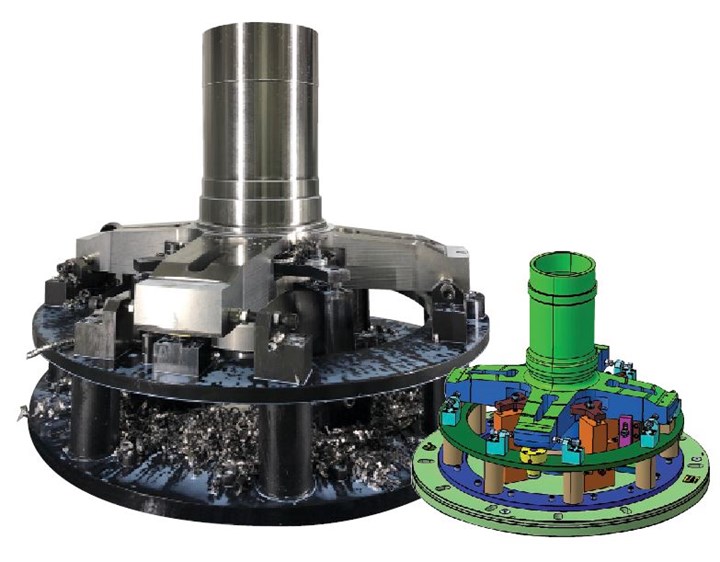
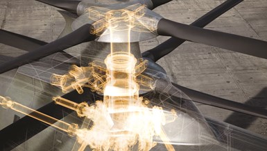
A digital twin of the rotor hub and its fixturing can be an aid for personnel replicating the setup in the real world. Digital twins also drive the simulations that set geometry targets for every phase of machining. Tool paths intentionally avoid portions of designs that are still in development.
The first two workpieces to emerge from the cell were a titanium rotor hub and an aluminum gearbox housing for Sikorsky’s Raider X, a prototype helicopter that is one of only two remaining contenders in a competition for a U.S. Army contract. As expected, comparing workpiece inspection data to digital models confirmed that the actual machining results were indistinguishable from the simulation.
The significance of this achievement cannot be understated, says Pete Germanowski, chief engineer for the Raider X. As the company’s bid for the Future Attack Reconnaissance Aircraft (FARA) program, which is part of the U.S. Army’s Future Vertical Lift effort to revolutionize its fleet, the Raider X represents a transformational shift in military aviation, he explains. It was a given that fulfilling expectations would also require a radical step forward in manufacturing capability. “As a competitive bidder on the FARA program, we had strict affordability, producibility, schedule and reliability goals to meet.”
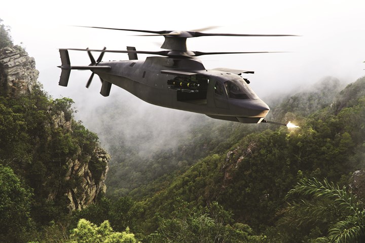
Shown here in an artist’s rendering, the Raider X has a top speed faster than 290 mph and a range of 400 miles. Powered by GE Aviation’s T901 jet turbine engine, currently rated at 3,000 hp on the rotor shaft, the aircraft can climb to 9,000 feet.
Advanced Aviation Meets Advanced Manufacturing
Designed to fly low and fast over terrain to avoid detection, the Raider X is a compound coaxial helicopter (CCH). This design is characterized by two sets of rotors mounted one atop the other on the same vertical shaft and spinning in opposite directions. Coaxial rotors add stability and maneuverability, and they overcome the tendency of a single set of rotors to lose lift at high speeds. Another prominent feature of the Raider X is the rear-facing propulsor, which replaces the laterally mounted tail propeller of a conventional helicopter. This push-propeller design helps pilots speed up or slow down without dipping or raising the nose.
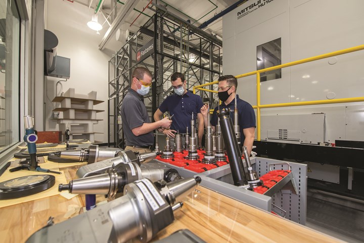
Left to right, Ryan Patry, manufacturing engineer, Pete Germanowski, chief engineer and Jason Pratts, manufacturing engineer, review cutting tools in the machining cell.
These advances in aviation link back directly to advanced technology in the machining cell, which produces eight unique part numbers for the main rotor, propulsor motor and main gearbox. For example, the two identical Fives Giddings & Lewis VTC 2500 vertical lathes are prized for their capability to accommodate a live milling head that enables machine timing holes and slots for the main shaft assembly in the same setup as turning operations. “The accuracy obtained by combining these operations is essential in the performance of a coaxial helicopter, because timing of the rotation of the rotors is the key to stable flight and precise hovering of the aircraft,” Patry explains.
Sikorsky’s Ryan Patry defines a digital twin as the current representation of a product in a digital form augmented with the as-designed/as-built data maintained throughout a product’s lifecycle.
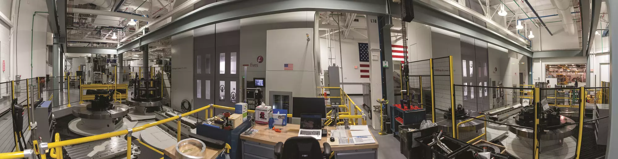
The cell’s other two machines, twin Mitsui Seiki HU 100-A-5X HMCs, offer the torque, rigidity and precision to cut titanium effectively, even in simultaneous five-axis operations. Occupying 36,259 dedicated, climate-controlled square feet, the cell also includes pallet systems for each VTL and an FMS for the two HMCs in order to run around-the-clock for three shifts. However, the “real story” is not the equipment, but “the operational characteristics of the cell,” Patry says. In fact, he calls it a “microcosm” of the overall digital manufacturing capability required to make the Raider X.
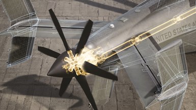
One benefit is of the digital twin is visualization of complex assemblies, such as this propulsor rotor drive train or the main rotor assembly pictured above
For example, engineers extensively employed 3D simulation to test, then modify designs based on input from technicians familiar with building, maintaining and flying helicopters. As a result, the helicopter is not only highly capable in flight, but also easy to assemble, repair and upgrade. In the machining cell, the same essential concepts enable reducing lead times by producing air-worthy components without cutting real test parts first. “We began roughing parts even as final design details still were being worked out, so parts are being produced much faster than on any previous development program,” Patry says.
The Cell in Operation
An observer on the shop floor likely wouldn’t notice anything remarkable about the metalcutting process itself. The splash of flood coolant and the staccato of chips hitting the sheet metal enclosure would seem quite normal for such large, powerful machines. At least on the surface, operations would seem to follow the typical three-phase sequence of roughing, semi-finishing and finishing.
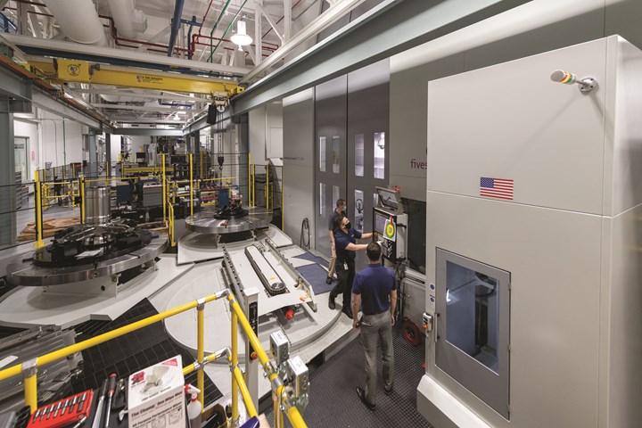
This VTC is served by an automated pallet changer. A second, identical VTC in the cell is similarly equipped. Both feature 2,500-mm (98.4 in.) tables, maximum turning swing of 1,560 mm (61.4 in.) and 1,750 mm (68.9 in.) of vertical Z-axis travel, as well as a hydrostatic ram for stiffness and X-axis travel left and right of center to cut (or probe) from either side.
However, the observer might be surprised to note that every machining operation is followed by a non-contact inspection to generate a 3D model of the workpiece. This is necessary because machining is governed by another 3D model derived not from a part scan, but from earlier simulations of that phase of the machining sequence. This latter model defines the geometry to be achieved in each operation.
Defining the geometry to be achieved makes this three-phase machining process different from the typical “rough, semi-finish, finish” progression. For example, phase-one “roughing” still aims to maximize material removal, but the goal is more ambitious than achieving a loose approximation of the final part shape. Rather, the workpiece must precisely match the governing 3D model. When and where to leave extra stock on that model depends on which portions of the design are still in development and must be “protected” when machining begins.
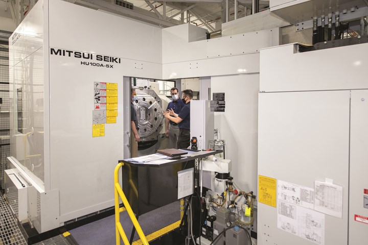
The engineering team reviews machining progress of a spur cover. Each of the cell’s twin five-axis HMCs has a 1,000-mm (39.4-in.) square trunnion table, X-axis travel of 1,300 mm (51.2 in.), and 1,000 mm (39.4 in.) of travel for both the Y and Z axes. The spindle has a double-contact custom toolholder interface and is rated at 37 Kw (50 hp).
This strategy enables configuring all the necessary manufacturing infrastructure, including NC programs, cutting tools and fixtures, weeks before designs are finalized rather than weeks later. Meanwhile, programmers can set about optimizing the next phase of machining. For example, 3D models of the as-machined gearbox from phase one helped refine and validate the accuracy of phase two machining in about 48% less time than similar projects in the past, Patry says. Among other opportunities, programmers discovered that certain fixtures from phase one could be used again.
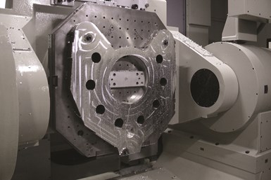
An inspection generates a “heat map” to validate the accuracy of the metal removal process before this spur cover proceeds to the next machining operation.
In every phase, color-coded heat maps of the workpiece make discrepancies between as-machined part models and simulation-derived governing models easy to spot. Shades of red and orange indicate the presence of material outside the tolerance band, perhaps due to tool deflection, clamping forces or
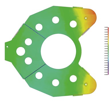
residual material stresses. If necessary, investigating and correcting the root causes of these discrepancies prevents parts from moving to the next stage until the workpiece matches the engineering model. At the same time, the digital process can be updated to reflect real-world performance. For instance, tool deflection can be quantified and accounted for in future simulations.
This iterative approach eliminates part rejects and rework. In the process, it yields significant reductions in lead time because the first machined part can be sent directly to assembly (or for testing). The main gearbox produced on the HMC is a case in point. Machining of the first piece began in July of 2020, approximately 10 weeks before design work for that part was finalized.
“Not only is the first part produced faster, but also that part is a usable asset,” Patry says. “In the legacy approach, we would plan only for the second part produced to be usable – and that second part might be produced three or four months after the first.”
In short, to say “We cut before we cut” in this factory is clearly both sensible and accurate.
Proof of Concept
The success of this machining cell is the culmination of Sikorsky’s digital factory concept, Patry says. “We consider it proof that our intelligent factory framework and our digital model-based environment is sound and highly effective. The Raider X is a winner because the factory building it is a winner.”
Sikorsky’s intelligent factory framework enables product designers, process planners, part programmers and managers of every manufacturing department to work together in a common, unified digital environment. The advantages of working within this intelligent factory framework are reflected in the behind-the-scenes activities leading up to chip cutting in the machining cell.
The core of the digital manufacturing environment in which the Raider X is being developed is Dassault 3DX design and manufacturing software. It is the repository of the virtual Raider X design — a 3D model of every component in the aircraft. Patry refers to this integrated database as a “single source of truth” for the entire program team, and it is constantly refreshed and refined by relevant input.
Simulations and digital twins enabled the company to lay out and set up a hanger for assembly of the Raider X well before the first fuselages arrived.
Components to be machined can be worked on in the digital-twin environment as virtual prototypes around which shopfloor processes are developed. Simulation of these processes involves 3D models of the entire process, including exact representations of machine structures and their kinematics to replicate how a cutting tool responds to servo commands. The case is the same for cutting tool assemblies, including geometry of all inserts, tool bodies and holders. “This data is defined in the 3D models and creates an unbroken thread from the NC program to the physical cutting tool setup and to the machine controller,” Patry says. “These critical data points are automatically verified and validated before the machine starts using that cutting tool.”
All these 3D models come together in Vericut simulation software to create virtual machining scenarios that programmers use to optimize the process. Ultimately, the results of simulations are embodied in the virtual models that define how the part should look at different stages of machining. Capability for multiple programmers to work on the same part at different stages also reduces lead time. “We used to have one NC programmer work an entire part, so delays occurred between operations,” Patry explains. “By working in three distinct machining phases, we can assign an NC programmer to each phase, because we have a virtual model for each phase. More people can perform at the same time.”
Beyond Machining
The machining cell will be enhanced with additional capabilities, potentially including robotics or other additional automation, as they become available. Its construction follows a “building block” approach that makes it easy to integrate more machines or to duplicate, whether at Lockheed Martin or at a supplier’s facility. The cell is also serving as a conceptual prototype for additional machining cells in Sikorsky’s digital factory. Although these cells differ from the Mitsui/G&L cell in many respects, they will nonetheless embody and expand on already proven digital capabilities.
The same concepts and capabilities are also at work beyond CNC machining. Other cells are already in operation for composite part construction, gear production and assembly, and all share the same philosophy of digital connectivity and integration. In fact, simulations and digital twins enabled the company to lay out and set up a hanger for assembly of the Raider X well before the first fuselages arrived. In addition to assembly methods, methods for transporting parts and checking assembly steps for compliance had already been optimized for efficiency and safety in the virtual space.
In many instances, using 3D augmented reality revealed issues that could be addressed easily in the planning stages. Perhaps an aisle needed to be widened or the height of a work platform made easier to adjust for the assembler’s reach or comfort. “This simulation was a very powerful tool, allowing the entire team to see how the aircraft was to be built, all during the conceptual design phase,” Germanowski says.
Patry acknowledges that Sikorsky has developed a number of proprietary innovations that significantly enhanced how its intelligent factory framework improves machine performance on the shop floor. As an example, he cites new ways to download and update essential data related to machining parameters. And yet, he emphasizes that the most important factor in success has not been any “secret sauce.” Rather, it is the fact that everyone has adopted and embraced a digital approach that enables them to collaborate more effectively, and, by extension, make “we cut before we cut” a reality. At Sikorsky, digital manufacturing is viewed as a team effort involving everyone, from design and manufacturing engineers to operations staff and facilities managers.


Related Content

Benefitting From an Accurate Data Ecosystem
Data is useless unless it’s true. After decades of false starts with incomplete, unstandardized data collection systems, Alexandria Industries put together a software ecosystem that delivers accurate data to managers, operators and ERP systems alike. In this article, discover its effect on the Alexandria shop floor.
Read More
Enhancing the Shop Floor with AI
How can AI and digital twins use data gathered on the shop floor? Learn how these digital tools can improve efficiency through programming, maintenance, sustainability and more.
Read More
Precision Shop Adopts Machine Monitoring, Boosts Revenue
Adopting machine monitoring helped LeClaire Manufacturing boost its vertical CNC utilization rates 38 percentage points and gain millions in revenue.
Read More
Protecting Your Automation Investments
Shops need to look at their people, processes and technology to get the most of out their automation systems.
Read MoreRead Next

Machining Demonstration Shows the Digital-Twin Concept in Action
A demonstration at IMTS 2018 showed that all of the pieces to meet the “Grand Challenge” are now in place, making so-called digital-twin manufacturing feasible for shops looking to streamline production of complex workpieces.
Read More
Digital "Fingerprints" Put Twins in Perspective
Unique identifiers keep the digital thread intact through design, production and quality control.
Read More